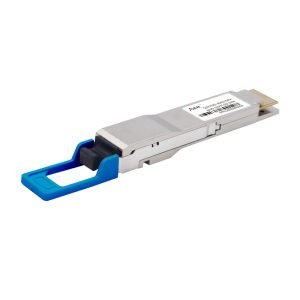
QSFP28-100G-ER4 100G Module 40KM
Optical SFP Module
100Gbps QSFP28 ER4 Transceiver, SM, 40KM
Share on
QSFP28-100G-ER4
100Gbps QSFP28 ER4 Transceiver, SM, 40KM
Features
- Support line rates from 103.125 Gbps to 111.81 Gbps
- Transmitter: cooled 4x25Gb/s LAN WDM EML TOSA (1295.56, 1300.05, 1304.58, 1309.14nm)
- Receiver: 4x25Gb/s SOA+PIN
- 4x25G electrical interface
- LC duplex receptacle
- Up to 40km reach for SMF
- Compliant with QSFP28 MSA
- Hot Pluggable QSFP28 form factor
- Digital Diagnostics Monitoring Interface
- Power dissipation < 4.0 W
- Compatible with RoHS
- Commercial operating case temperature: 0 to +70°C
Application
- Ethernet 100GBASE-ER4
- Infiniband QDR and DDR interconnects
- Client-side 100G Telecom connections
- Data Center
Standard
- Compliant with IEEE 802.3bm
- Compliant with QSFP28 MSA
- Compliant with SFF-8436
Absolute Maximum Ratings
| Parameter | Symbol | Min | Max | Unit |
| Power Supply Voltage | Vcc | -0.5 | 3.6 | V |
| Damage Threshold, each Lane | THd | -3 | dBm | |
| Storage Temperature | Ts | -40 | +85 | °C |
| Operating Humidity | – | 5 | 95 | % |
Recommended Operating Conditions
| Parameter | Symbol | Min | Typical | Max | Unit |
| Operating Case Temperature | Tc | 0 | 70 | ℃ | |
| Power Supply Voltage | Vcc | 3.135 | 3.3 | 3.465 | V |
| Power Supply Current | Icc | 1360 | mA | ||
| Data Rate,each Lane | 25.78125 | Gbps | |||
| Control Input Voltage High | 2 | Vcc | V | ||
| Control Input Voltage Low | 0 | 0.8 | V | ||
| Data Rate Accuracy | -100 | 100 | ppm | ||
| Link Distance with SMF (without FEC) | D1 | – | 30 | km | |
| Link Distance with SMF (with FEC) | D2 | 40 | km |
Optical Characteristics
| Optical Transmitter Characteristics | |||||||
| Parameter | Symbol | Min | Typical | Max | Unit | Notes | |
| Launched Power (avg.) | Pavg | -2.5 | 4.5 | dBm | |||
| Total Output. Power | Pout | 10.5 | dBm | ||||
| OMA, each Lane | POMA | 0.1 | 4.5 | dBm | |||
| Difference in Launch Power
between any Two Lanes (OMA) |
Ptx,diff | 3.6 | dB | ||||
| Launch Power in OMA minus
Transmitter and Dispersion Penalty (TDP), each Lane |
-0.65 | dBm | |||||
| Wavelength Assignment | λ0 | 1294.53 | 1295.56 | 1296.59 | nm | ||
| λ1 | 1299.02 | 1300.05 | 1301.09 | ||||
| λ2 | 1303.54 | 1304.58 | 1305.63 | ||||
| λ3 | 1308.09 | 1309.14 | 1310.19 | ||||
| TDP, each Lane | TDP | 2.5 | dB | ||||
| Spectral Width(-20dB) | ∆λ | 1 | nm | ||||
| Side Mode Suppression Ratio | SMSR | 30 | dB | ||||
| Extinction Ratio | ER | 7 | dB | ||||
| Transmitter OFF Output Power | POff | -30 | dBm | ||||
| RIN20 OMA | RIN | -130 | Ohm | ||||
| Output Eye Mask definition
{X1, X2, X3, Y1, Y2, Y3} |
{0.25, 0.4, 0.45, 0.25, 0.28, 0.4} | ||||||
| Optical Receiver Characteristics | |||||||
| Parameter | Symbol | Min | Typical | Max | Unit | Notes | |
| Damage Threshold, each Lane | THd | -3 | dBm | ||||
| Average Receive Power, each Lane | -16.9 | -4.9 | dBm | @30km | |||
| Average Receive Power, each Lane | -20.9 | -4.9 | dBm | @40km | |||
| Receive Power (OMA), each Lane | -1.9 | dBm | |||||
| Receiver Sensitivity (OMA), each
Lane |
SEN1 | -14.5 | dBm | For BER
= 1×10-12 |
|||
| Stressed Receiver Sensitivity
(OMA), each Lane |
-12.5 | dBm | For BER
= 1×10-12 |
||||
| Receiver Sensitivity (OMA), each
Lane |
SEN2 | -18.5 | dBm | For BER
= 5×10⁻⁵ |
|||
| Stressed Receiver Sensitivity
(OMA), each Lane |
-16.65 | dBm | For BER
= 5×10⁻⁵ |
||||
| Receiver reflectance | -26 | dB | |||||
| Difference in Receive Power
between any Two Lanes (Average and OMA) |
Ptx,diff | 3.6 | dB | ||||
| LOS Hysteresis | LOSH | 0.5 | dB | ||||
| LOS | Optical De-assert | Pd | -24 | dBm | |||
| Optical Assert | Pa | -26 | |||||
| Receiver Electrical 3 dB upper
Cutoff Frequency, each Lane |
Fc | 31 | GHz | ||||
| Vertical Eye Closure Penalty, each
Lane |
1.5 | dB | |||||
| Stressed Eye J2 Jitter, each Lane | 0.3 | UI | |||||
| Stressed Eye J9 Jitter, each Lane | 0.47 | UI | |||||
Ordering information
| Part. No | Specifications | ||||||||
| Pack | Rate
(Gbps) |
Tx
(nm) |
Po
(dBm) |
RX | Sen
(dBm) |
Temp
(℃) |
Reach
(km) |
DDM | |
| QSFP28-100G-ER4 | QSFP28 | 100G | EML LWDM | -2.5~4.5 | SOA+PIN | <-18.5 | 0~70 | 40 | Y |


